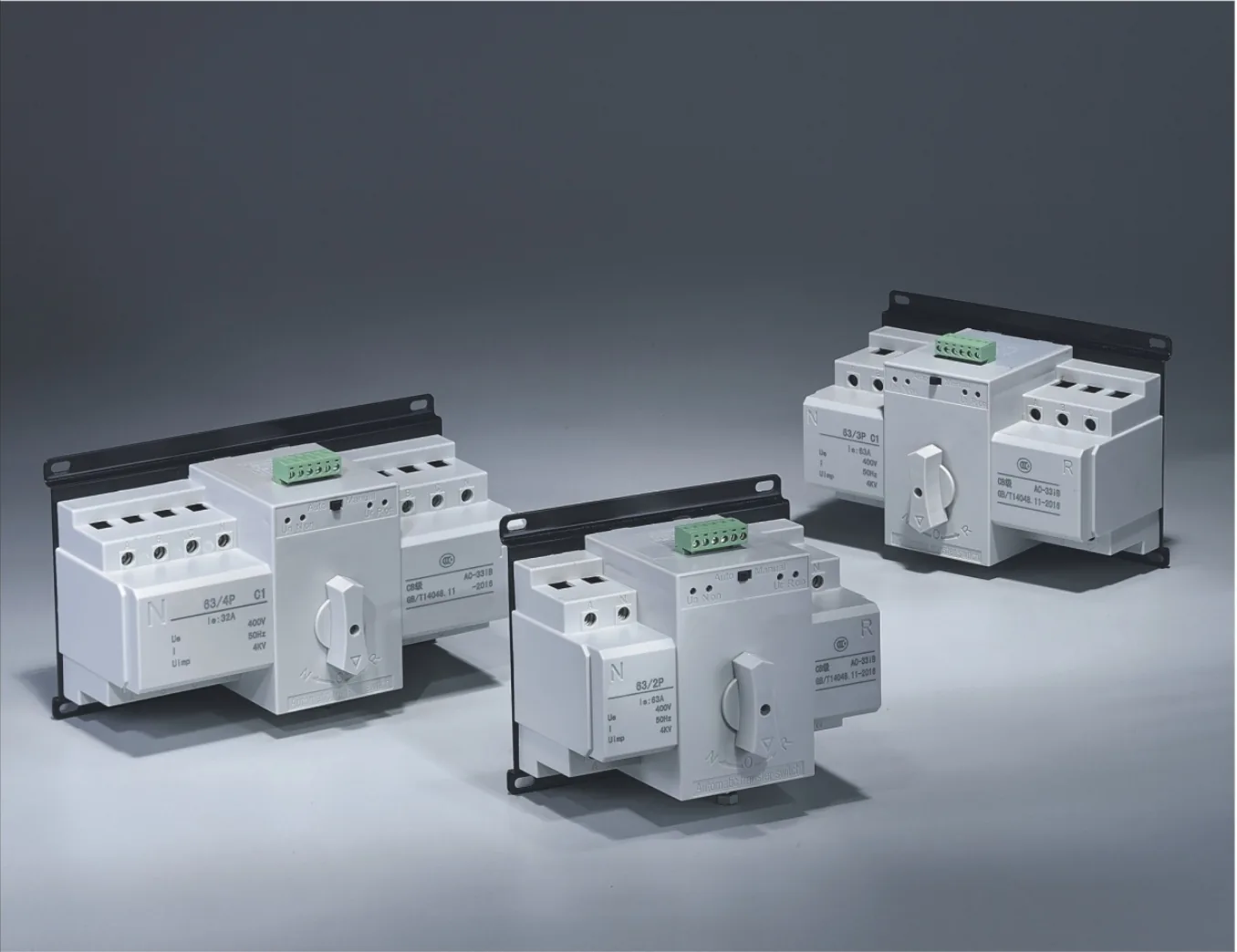
63 Series MCB-Type Automatic Transfer Switch (ATS)
MCB-based automatic transfer switch for lighting and small-motor control. 10–63 A, 2/3/4 poles by type, CB class, AC-33B.
PC-class automatic transfer switch for mains/standby changeover. 3 or 4 poles, 20–3200 A series, with frame-specific ratings and wiring options.
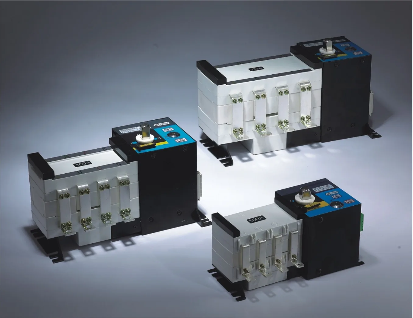
Model: Isolating-Type Automatic Transfer Switch
PC-class automatic transfer switch for mains/standby changeover. 3 or 4 poles, 20–3200 A series, with frame-specific ratings and wiring options.
| Product type | Isolating-type automatic transfer switch (ATSE), PC class |
|---|---|
| Series current range | 20–3200 A; select the required frame and utilization category |
| Rated operational voltage Ue | AC 400 V |
| Rated frequency | 50 Hz |
| Number of poles | 3-pole or 4-pole |
| Switching positions | I–0–II: normal supply / OFF / standby supply |
| Supply arrangements | Mains-to-mains or mains-to-generator |
| Control voltage options | DC 24 V, DC 48 V, DC 110 V or AC 220 V; specify the required option |
| Transfer time, I–II / II–I | 20–250 A: 0.45 s; 400–630 A: 0.6 s; 800–1600 A: 1.2 s |
| Control-circuit connection | Plug-in terminals; arrangement depends on control configuration |
A dual power automatic transfer switch (ATS) for automatic changeover between a normal supply and a standby supply in AC 400 V, 50 Hz distribution systems. The integrated switch and control mechanism supports mains-to-mains and mains-to-generator applications, with electrical and mechanical interlocking.
Available in 3-pole and 4-pole configurations, the series uses three stable positions: I — normal supply; 0 — both sources OFF; II — standby supply. Select the frame, current rating and control arrangement for the installation.
The contact system uses a double-row composite-contact arrangement. A single-motor, gear-driven mechanism operates the spring-energy-storage switching assembly. The control assembly is housed in a metal enclosure, with glass-fibre-reinforced unsaturated polyester insulating components for the switching assembly.
Integrated detection: Voltage and frequency detection are integrated with the switching and control mechanism.
Integrated electronic logic control provides anti-interference capability.
For normal/standby distribution and generator changeover in hospitals, banks, high-rise buildings, power distribution and automation systems. It can also be used for isolation and infrequent circuit switching. Choose the transfer arrangement and downstream protection for the load; this is a transfer switch, and transfer involves the switching times listed below.
Specify the frame/current rating, 3 or 4 poles, control type and quantity. The ordering structure identifies the isolating-type transfer switch, frame size, pole count and rated working current.
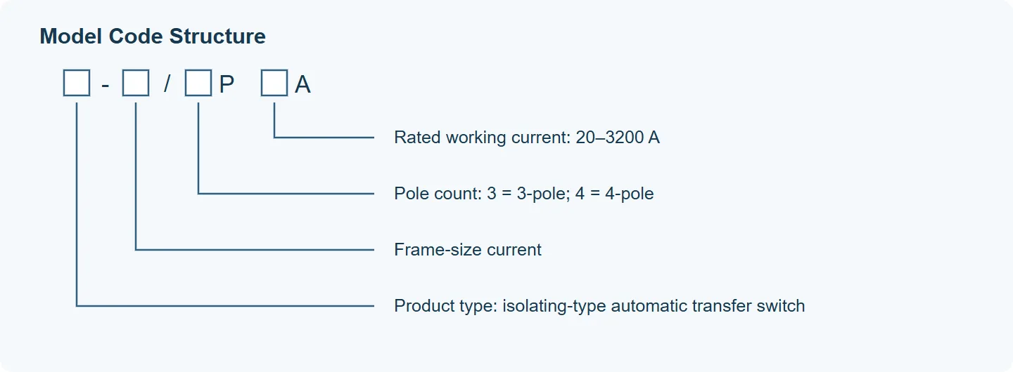
Model-code layout: product type, frame-size current, number of poles and rated working current. Select the image to enlarge.
| Field, from left to right | Meaning |
|---|---|
| Product type | Isolating-type automatic transfer switch |
| Frame-size current | Frame current rating |
| Pole count, P | 3 = 3-pole; 4 = 4-pole |
| Rated working current, A | 20–3200 A; select the required current rating |
| Item | Details |
|---|---|
| Control device | Built-in controller |
| Product structure | Compact, high-current, simple construction with integrated ATS control |
| Key characteristics | Fast switching, low failure rate, convenient maintenance and reliable performance |
| Wiring arrangement | Front-plate wiring |
| Transfer modes | Mains-to-mains or mains-to-generator; automatic transfer and automatic return |
| Frame sizes | 100, 160, 250, 400, 630, 1000, 1250, 1600, 2000, 2500, 3200 |
| Rated current options (A) | 20, 32, 40, 63, 80, 100, 125, 160, 200, 225, 250, 315, 400, 500, 630, 800, 1000, 1250, 1600, 2000, 2500, 3200 |
| Switch type | Load-switch type |
| Number of poles | 3-pole or 4-pole |
| Reference standard | GB/T 14048.11-2016 |
| ATSE class | PC class |
Design references: IEC 60947-1:1998 / GB/T 14048.1-2002; IEC 60947-3:1999 / GB 14048.3-2002; GB/T 14048.11-2016, covering low-voltage switchgear, switch-disconnectors and automatic transfer switching equipment.
The tables below cover the 20–1600 A ratings. Select the rated operational current for the required utilization category. Electrical ratings for the 2000–3200 A configurations must be confirmed with the quotation.
| Current (A) | AC-31A Ie (A) | AC-35A Ie (A) |
|---|---|---|
| 20 | 20 | 20 |
| 40 | 40 | 40 |
| 63 | 63 | 63 |
| 80 | 80 | 80 |
| 100 | 100 | 100 |
| 125 | 125 | 125 |
| 160 | 160 | 160 |
| 250 | 250 | 250 |
| 400 | 400 | 400 |
| 630 | 630 | 630 |
| 800 | 800 | 800 |
| 1000 | 1000 | 1000 |
| 1250 | 1250 | 1000 |
| 1600 | 1600 | 1600 |
| Current (A) | AC-33A Ie (A) | Weight (kg) |
|---|---|---|
| 20 | 20 | 7.0 |
| 40 | 40 | 7.2 |
| 63 | 63 | 7.2 |
| 80 | 80 | 7.2 |
| 100 | 100 | 7.5 |
| 125 | 125 | 7.5 |
| 160 | 160 | 8.8 |
| 250 | 250 | 9.0 |
| 400 | 400 | 16.5 |
| 630 | 400 | 17 |
| 800 | 630 | 32 |
| 1000 | 800 | 36 |
| 1250 | 800 | 40 |
| 1600 | 1000 | 43 |
| Current rating | Ui | Uimp |
|---|---|---|
| 20–125 A | 750 V | 8 kV |
| 160–250 A | 750 V | 8 kV |
| 400–630 A | 1000 V | 12 kV |
| 800 A | 1000 V | 12 kV |
| 1000–1600 A | 1000 V | 12 kV |
| Current rating | Transfer time; motor power |
|---|---|
| 20–125 A | I–II / II–I: 0.45 s. Motor start / normal: 300 / 55 W. |
| 160–250 A | I–II / II–I: 0.45 s. Motor start / normal: 325 / 62 W. |
| 400–630 A | I–II / II–I: 0.6 s. Motor start / normal: 335 / 74 W. |
| 800 A | I–II / II–I: 1.2 s. Motor start / normal: 400 / 90 W. |
| 1000–1600 A | I–II / II–I: 1.2 s. Motor start / normal: 440 / 98 W. |
Rated operational voltage: AC 400 V. Rated making capacity: 10 Ie. Rated breaking capacity: 8 Ie. Control-voltage options are DC 24 V, DC 48 V, DC 110 V or AC 220 V; these are separate nominal options.
The short-circuit figures below are distinct from the making and breaking capacities. Confirm the upstream protective-device coordination for the selected switch. A withstand duration is not specified here.
Limited short-circuit current and short-time withstand current are shown below.
| Current rating | Limited (kA) | Withstand (kA) |
|---|---|---|
| 20–125 A | 50 | 7 |
| 160–250 A | 50 | 9 |
| 400–630 A | 70 | 13 |
| 800–1000 A | 70 | 26 |
| 1250 A | 100 | 50 |
| 1600 A | 120 | 50 |
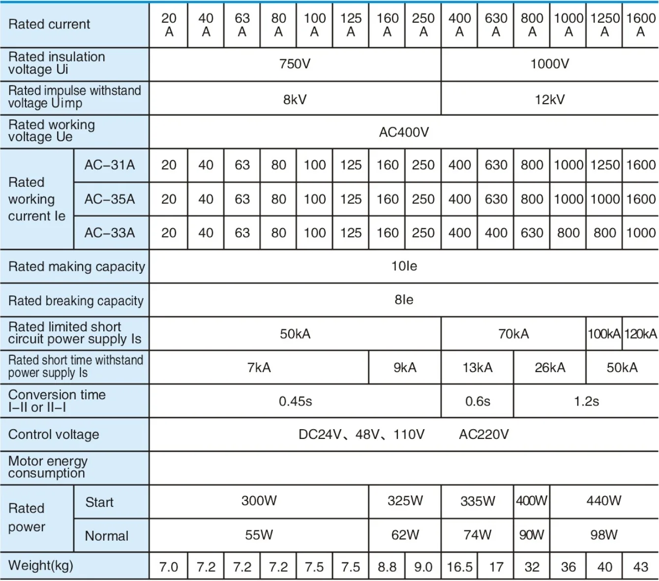
20–1600 A electrical performance matrix — select the image to enlarge.
The diagram identifies the normal and standby A, B, C and N terminals and the load connection. The drawing shows a four-pole arrangement; use the matching diagram for the ordered pole configuration.
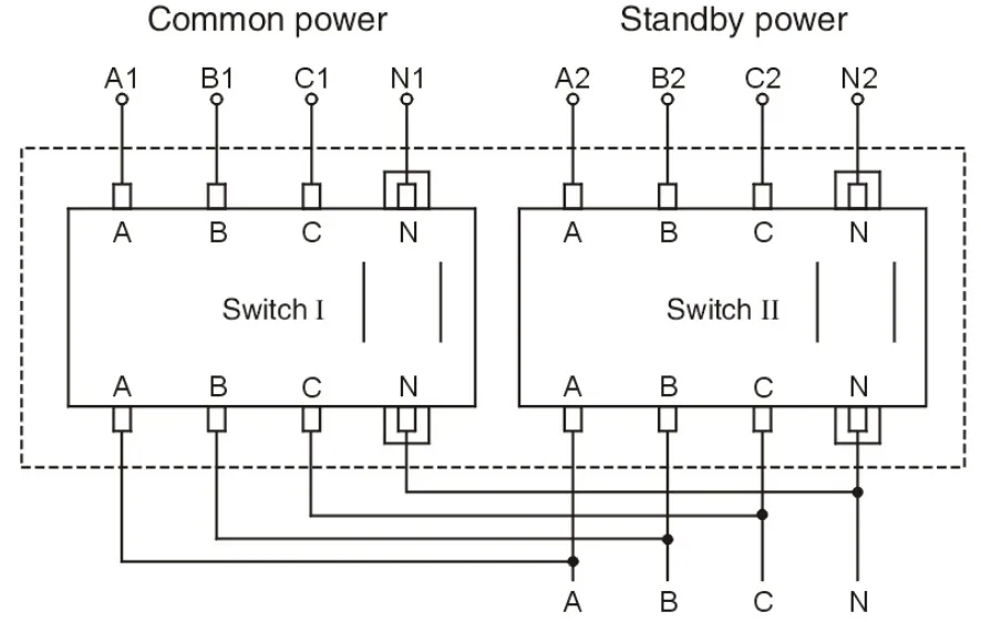
Normal supply, standby supply and load main-circuit arrangement — select the image to enlarge.
Select the dimensional variant by frame and number of poles. Lettered dimensions in each table correspond to its matching drawing. Allow space for the full handle movement and terminal connections.
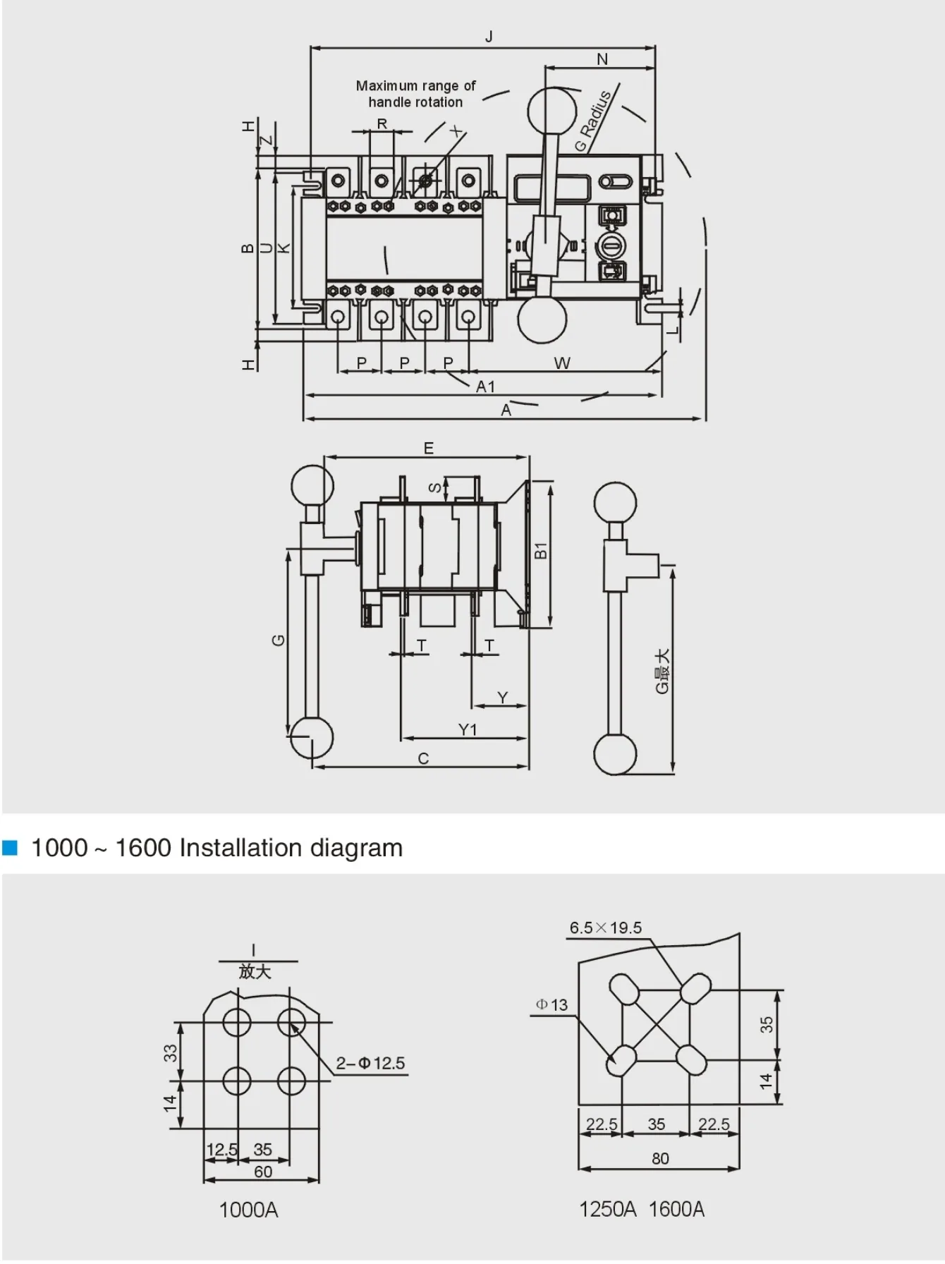
100–1600 frame drawings and 1000–1600 A terminal details — select the image to enlarge.
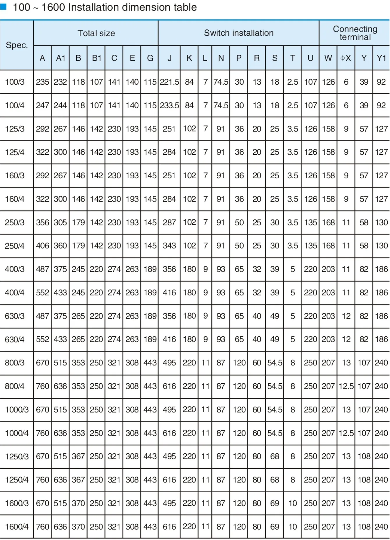
3-pole and 4-pole dimensional variants for 100–1600 frames — select the image to enlarge.
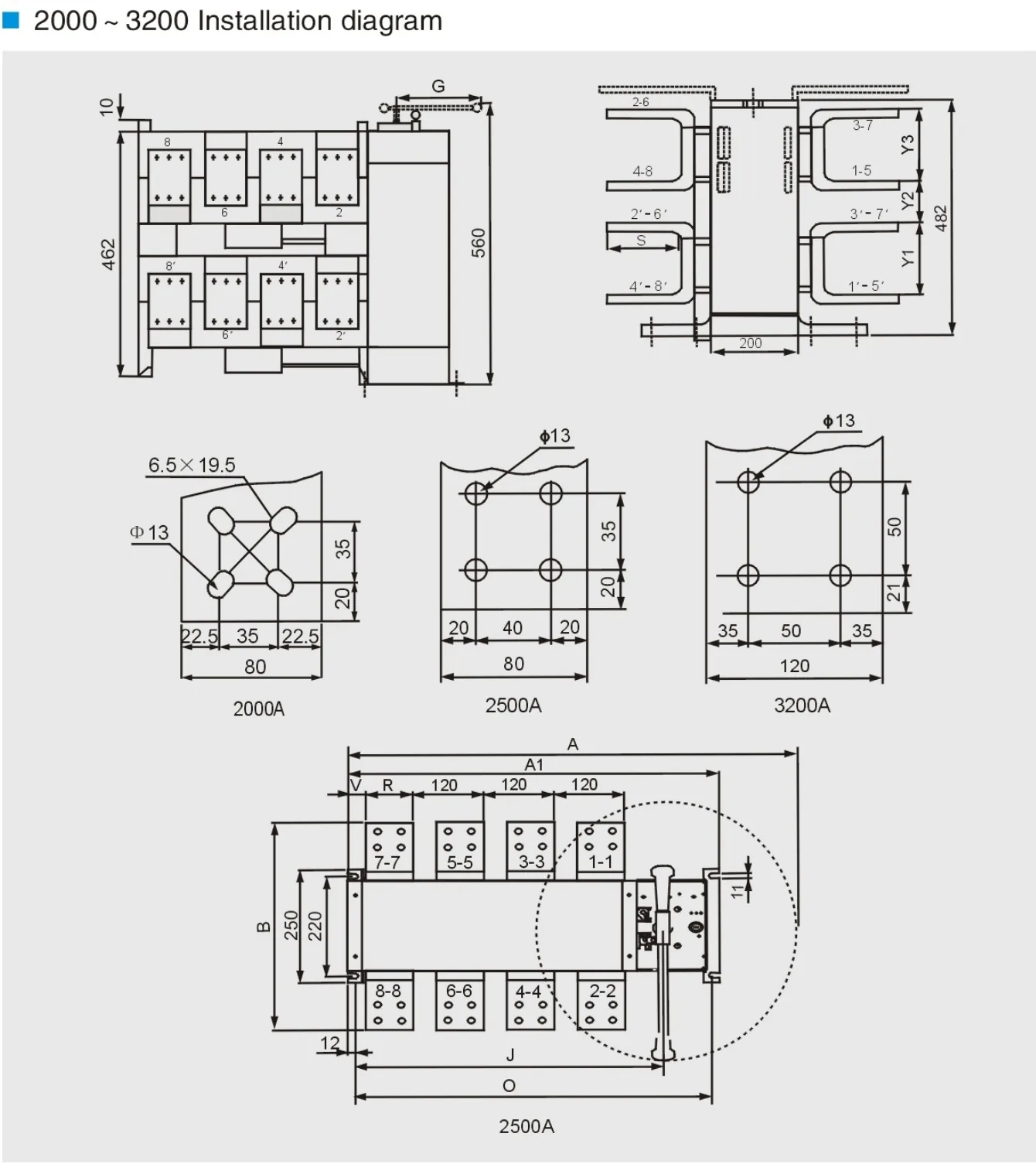
2000–3200 frame and terminal drawings — select the image to enlarge.
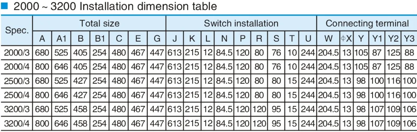
3-pole and 4-pole dimensional variants for 2000–3200 frames — select the image to enlarge.
Select one of the seven arrangements to match the ordered controller, frame and terminal configuration. The interfaces shown are configuration-specific. Electrical connections must be made by qualified personnel with the supplies isolated.
The economy-type arrangement uses one six-terminal group, 301–306. The control supply is internally connected to the main circuit. With both sources available, the normal source supplies the load. On normal-source failure, the switch transfers to an available standby source and returns when the normal source recovers. Optional external lamps indicate the selected source. Confirm the ordered economy-frame rating before choosing this arrangement. Optional switch-position indication connections are shown at terminals 302–305 in the economy-type diagram.
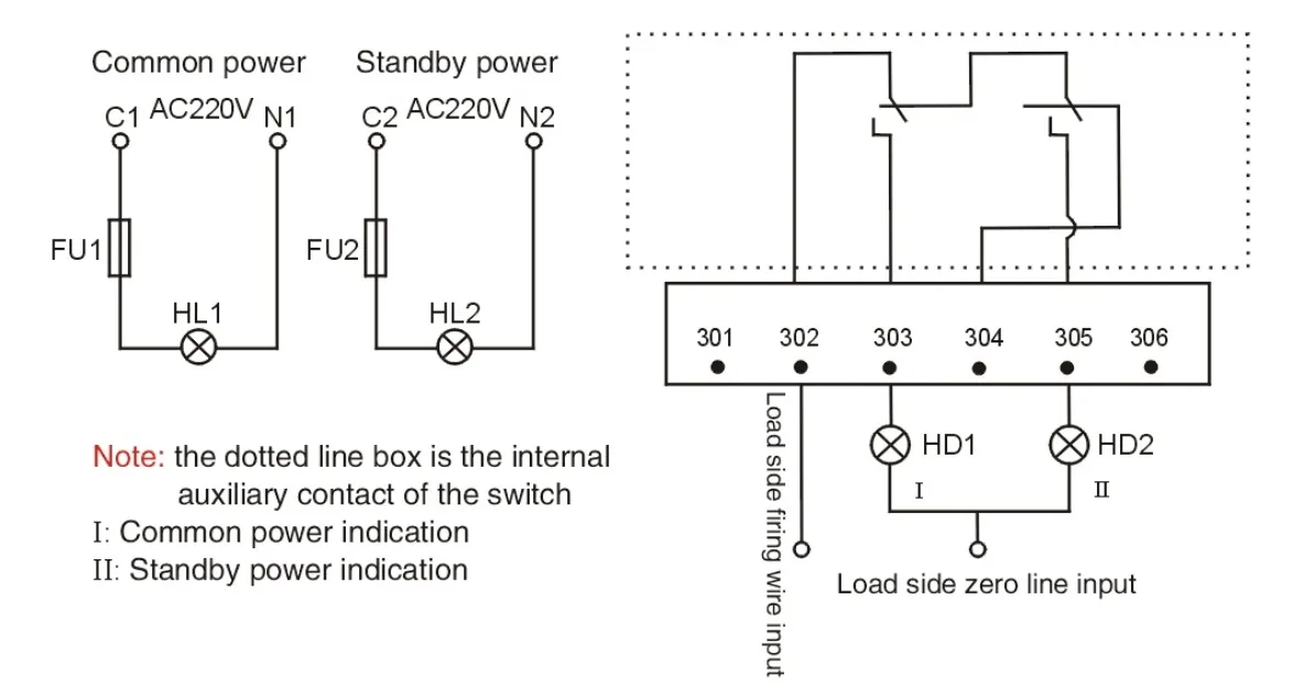
Economy-type terminal connection — select the image to enlarge.
This arrangement provides passive status contacts, a 24 V fire-signal input and a generator-start signal output. Its 301–308 terminal layout differs from the other arrangements.
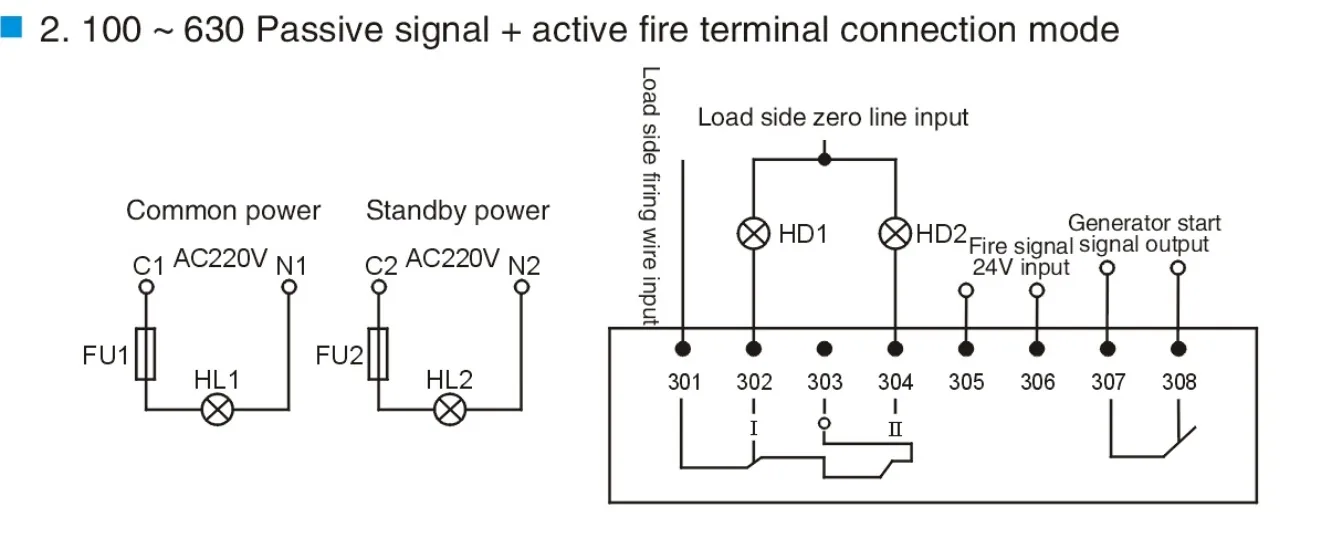
100–630: status signals and fire-control input — select the image to enlarge.
The fully automatic arrangement uses terminal groups 101–106, 201–206 and 301–306. FU1 and FU2 are 2 A fuses. Optional groups 401–406 and 501–506 are shown for switches above 1000 A.
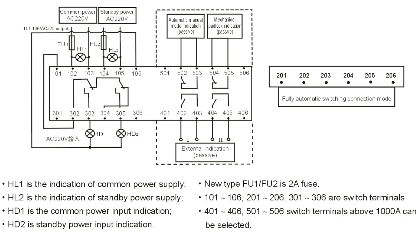
160–3200 A: fully automatic control — select the image to enlarge.
A separate passive forced-zero contact commands position 0 so both supplies are disconnected. Follow this configuration’s contact arrangement; it is different from the automatic-mode jumper arrangement.
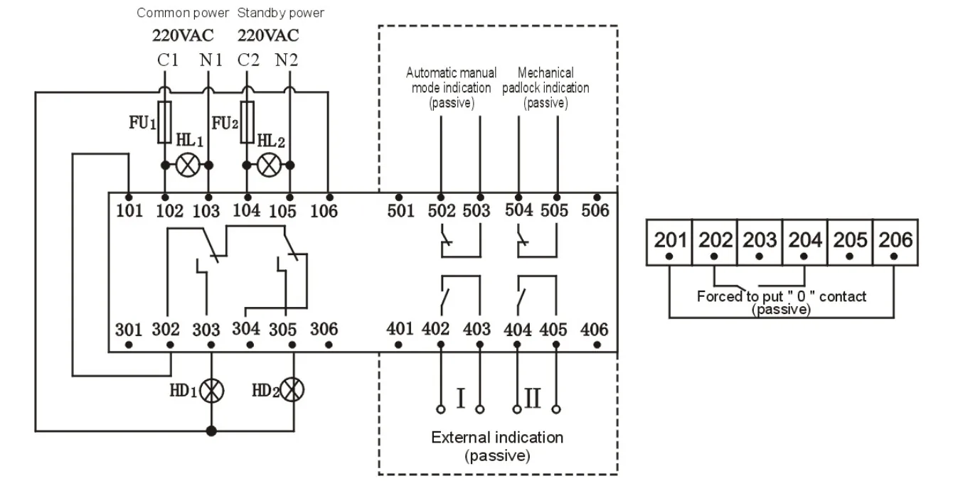
100–3200: automatic control with forced OFF — select the image to enlarge.
The K1 output provides the generator-start signal when the normal supply is absent. The diagram shows the 201–206 jumper for this automatic configuration.
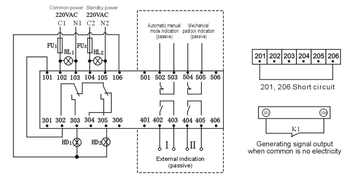
100–3200: automatic control with generator-start output — select the image to enlarge.
SA selects automatic or manual remote control. SB1 commands the normal source and SB2 commands the standby source through passive contacts.
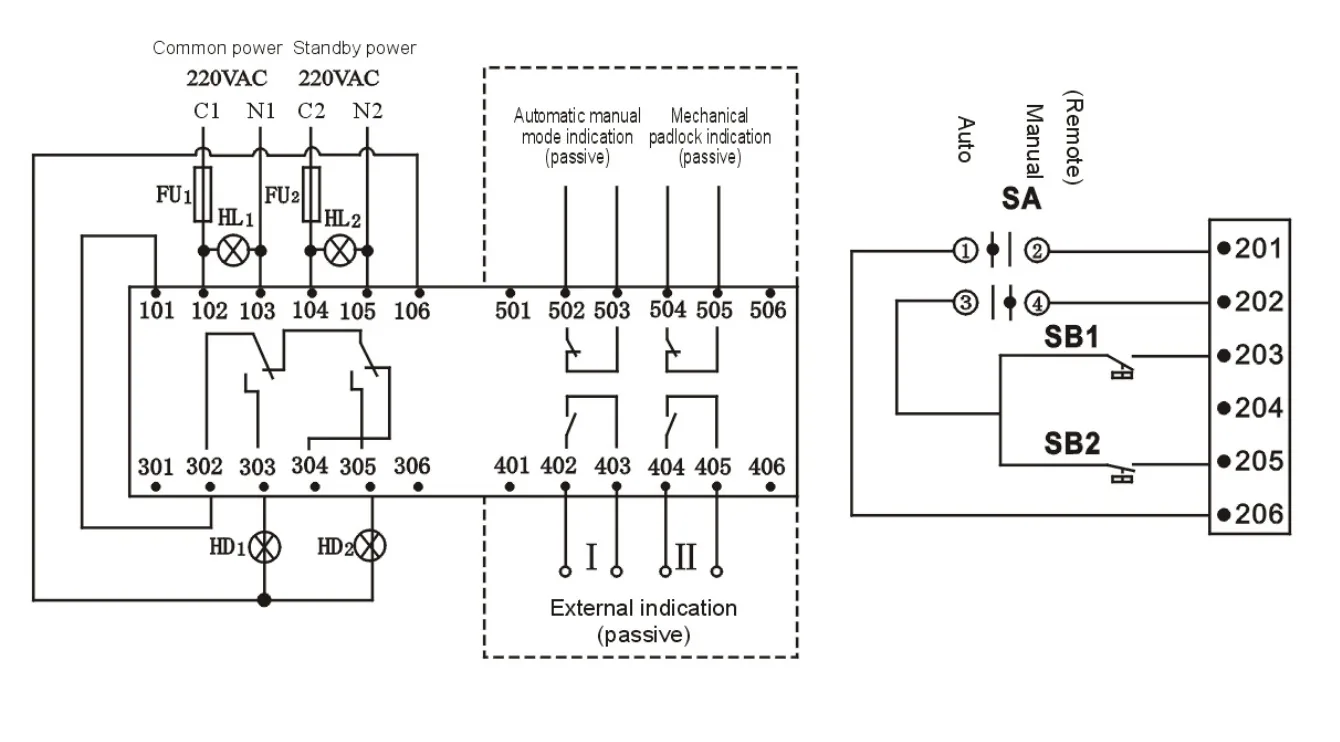
Automatic and remote manual control — select the image to enlarge.
In this controller-equipped configuration, terminals 102, 103, 104 and 105 do not require an external control supply. Optional groups 401–406 and 501–506 are available on switches above 1000 A. The K1 generator-start output is shown separately.
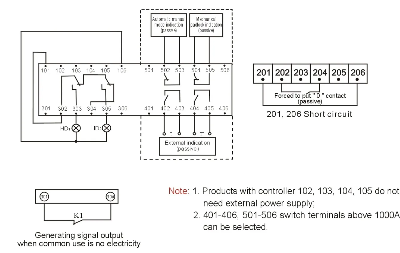
100–3200: controller-equipped configuration — select the image to enlarge.
| Marking | Function |
|---|---|
| C1 / N1; C2 / N2 | Normal-source line / neutral; standby-source line / neutral |
| HL1 / HL2 | Normal / standby supply-present indications |
| HD1 / HD2 | Normal / standby switch-position indications |
| FU1 / FU2 | 2 A control-circuit fuses |
| 101–106; 201–206 | Secondary/control terminal groups |
| 301–306 | External indication terminal group |
| 401–406; 501–506 | Optional auxiliary terminal groups; availability depends on frame/configuration |
| K1 | Generator-start signal on loss of the normal source |
| SA; SB1 / SB2 | Auto/manual selector; normal / standby manual commands |
Press the terminal release in the indicated direction with a screwdriver and insert the prepared conductor. The stripping length is 8–9 mm; retain the conductor-diameter marking shown in the drawing when selecting the terminal wire.
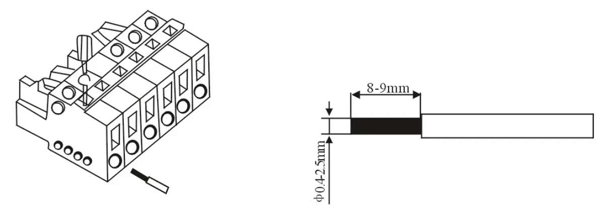
Control-terminal insertion and stripping dimensions — select the image to enlarge.
Mounting orientations A, B and C are permitted. A is preferred. Orientation D is not permitted.
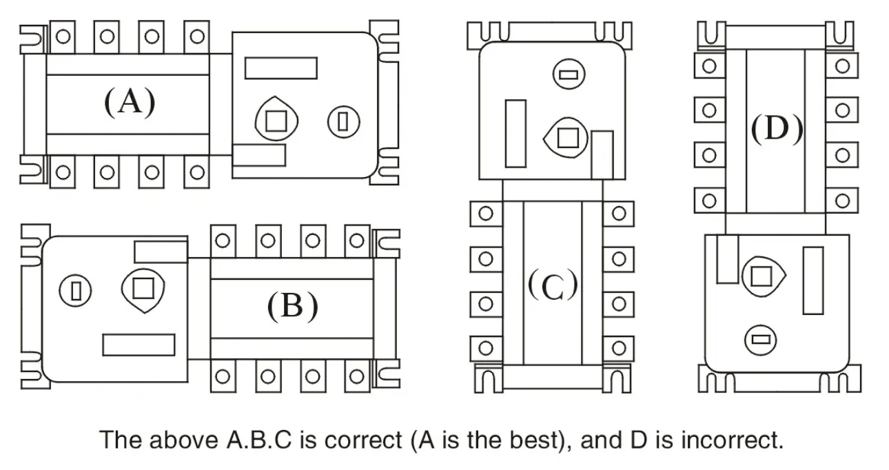
Permitted and incorrect mounting orientations — select the image to enlarge.
When requesting a quotation or placing an order, please specify:
Example configuration: 250 A, 4-pole, fully automatic transfer switch. This is an order-description example.
For selection assistance, also tell us whether the project uses mains-to-mains or mains-to-generator transfer, the supply voltage and frequency, required control voltage and any fire-control, generator-start or remote-control interface.
MCB-based automatic transfer switch for lighting and small-motor control. 10–63 A, 2/3/4 poles by type, CB class, AC-33B.
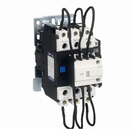
Inrush Current Protection: Integrated resistors/Reactors limit switching surges.
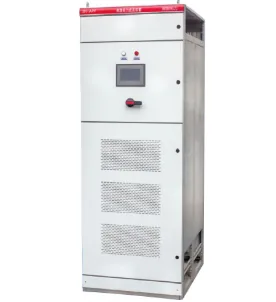
APF Active power filter device integrates one or multiple active power filter modules, a control unit, circuit breakers, contactors, a cooling system, and other core components into a standard industrial enclosure, forming a complete, plug-and-play harmonic mitigation solution.