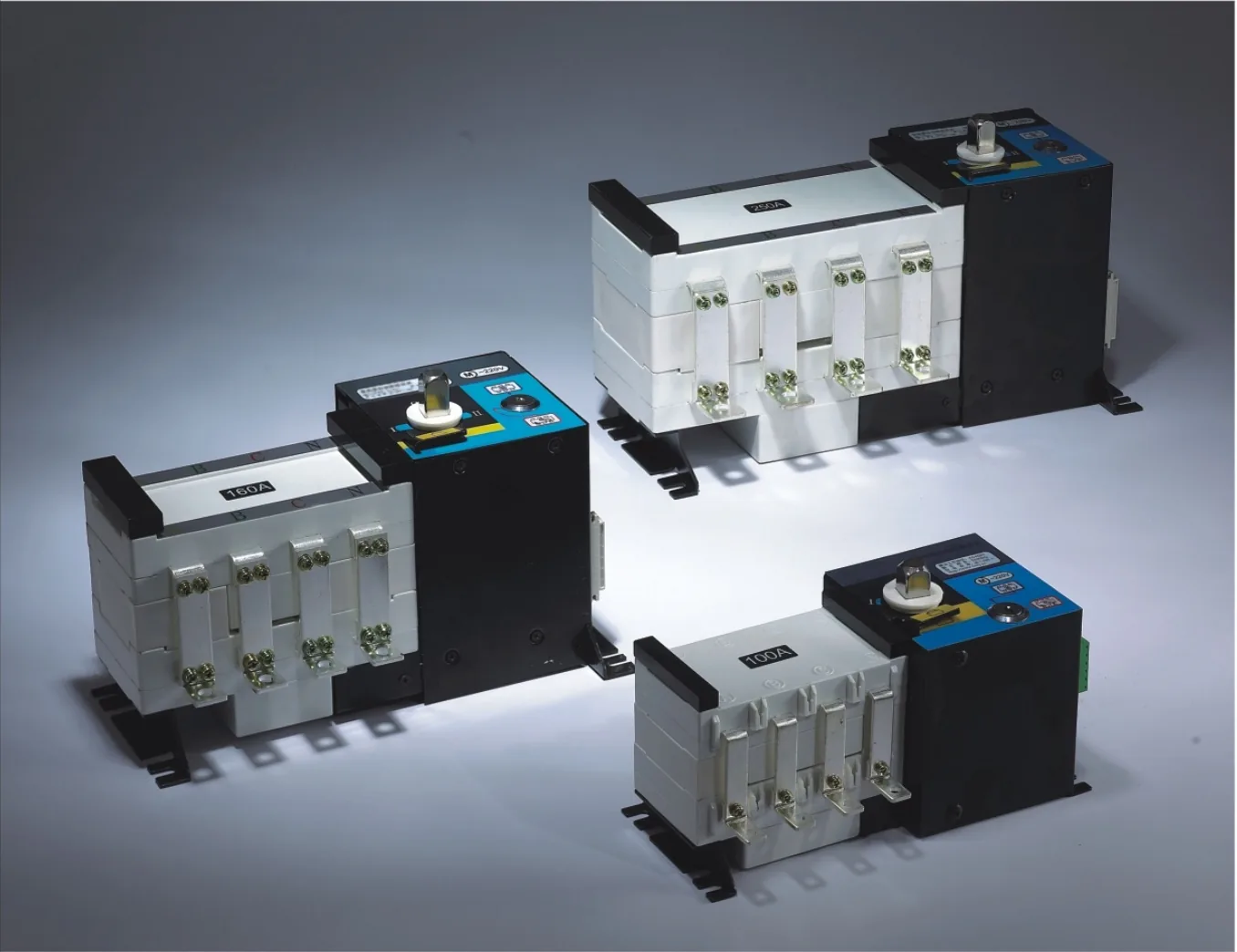
Isolating-Type Automatic Transfer Switch (ATS)
PC-class automatic transfer switch for mains/standby changeover. 3 or 4 poles, 20–3200 A series, with frame-specific ratings and wiring options.
MCB-based automatic transfer switch for lighting and small-motor control. 10–63 A, 2/3/4 poles by type, CB class, AC-33B.
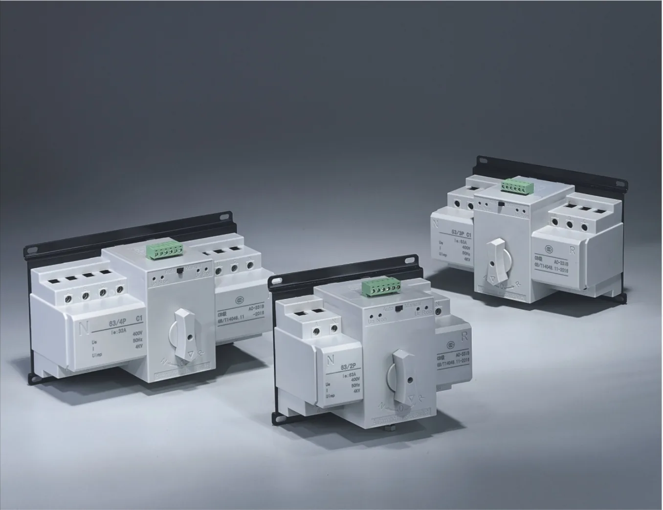
Model: 63 Series MCB-Type Automatic Transfer Switch
MCB-based automatic transfer switch for lighting and small-motor control. 10–63 A, 2/3/4 poles by type, CB class, AC-33B.
| Product type | Miniature-circuit-breaker (MCB) automatic transfer switch; CB class |
|---|---|
| Series/frame designation | 63 series |
| Rated operating current range | 10–63 A |
| Number of poles | 2-pole, 3-pole or 4-pole; availability depends on variant |
| Type options | A, C, C1, D, F and Z |
| Utilization category | AC-33B |
| Controller and drive supply | AC 220 V, derived from incoming phase A and neutral |
| Normal-source sensing criterion | Phase A–neutral; normal-source criterion AC 190–240 V |
| Operation | Automatic or manual |
| Controller fuses | Two 1 A fuses |
| Indication outputs | AC 220 V / 150 mA reference for 220 V versions; F-type diagrams specify AC 230 V |
| Reference standards | GB 14048.11 and IEC 60947-6-1 |
A miniature circuit breaker automatic transfer switch for normal and standby power changeover. This CB-class dual power automatic transfer switch uses two miniature circuit breakers, auxiliary and alarm contacts, an interlocked drive mechanism and a controller. The 63 series covers a 10–63 A operating-current range and is intended particularly for lighting and small-motor control equipment.
The 63 series includes A, C, C1, D, F and Z types. Select the current rating, pole count and control interface for your application. The utilization category is AC-33B; reference standards are GB 14048.11 and IEC 60947-6-1.
For lighting and small-motor control projects, start with the load current, pole count and required control interface. Send the details below so the matching type and ordering configuration can be confirmed.
| Selection item | What to provide |
|---|---|
| Current requirement | 10–63 A series. Give both normal and standby breaker ratings if they differ. |
| Pole count | Request 2, 3 or 4 poles; the matching type and configuration must be confirmed. |
| Site supply | Provide the normal and standby system voltages and frequency. |
| Control interfaces | Choose basic status indication, fire-control input or generator-start signal, as applicable to the type. |
| Installation | Describe the mounting space and any special installation or operating conditions. |
| Quotation details | Send the quantity and destination country. |
Email for ATS Selection · Discuss Your Configuration on WhatsApp
| Type group | Available arrangements |
|---|---|
| A / C / C1 / Z | Basic indication or a fire-control/generator terminal version; match the selected terminal arrangement. |
| F | General or intelligent output version. The intelligent diagram includes a DC 24 V fire input; F indication drawings specify AC 230 V. |
| D | Indication outputs with optional fire-control and generator signals. Confirm the supplied terminal arrangement and fire-input polarity. |
The table identifies the interfaces illustrated for each type. Use the detailed dimensions and terminal diagram for the selected configuration before installation.
Comparing ATS constructions? View the PC-class isolating-type ATS for its separate current range, pole options and control arrangements.
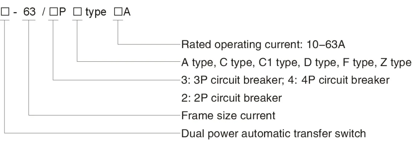
63 series model and configuration fields — select the image to enlarge.
| Field | Meaning |
|---|---|
| Product type | Dual power automatic transfer switch. Confirm the complete ordering code with the requested configuration when placing an order. |
| Frame designation | 63 |
| Pole count, P | 2 = 2-pole; 3 = 3-pole; 4 = 4-pole |
| Type designation | A, C, C1, D, F or Z |
| Rated operating current, A | 10–63 A |
The assembly provides compact, straightforward operation and a single-motor drive with low-impact movement. Circuit-breaker open/closed status can be brought to the user terminals, with corresponding indications on the ATS panel. Select the normal and standby breaker ratings separately when the application requires different ratings.
The controller and driving mechanism use AC 220 V taken from incoming phase A and neutral of the normal or standby supply. Automatic selection is based on the A–N sensing supply:
In manual mode, operation is possible whether the sources are energized or not. Set the manual/automatic selector to manual before using the handle.
| Handle movement | Switch position |
|---|---|
| Clockwise to the end stop | Normal breaker closes; standby breaker opens |
| Counterclockwise to the end stop | Standby breaker closes; normal breaker opens |
In automatic mode, an available normal supply is selected; when the normal supply fails under the described sensing condition, an available standby supply is selected. The corresponding source indication is shown on the panel.
The ATS includes two 1 A fuses and an electrical connector; the fuses provide short-circuit protection for the automatic-controller circuit. The 220 V indication-output description specifies AC 220 V and 150 mA; these are powered indication outputs rather than voltage-free contacts. The F-type drawings specify AC 230 V for their indication outputs. Use the matching output rating and terminal arrangement for the selected type; do not apply an external supply to a powered indication output.
The diagram identifies normal supply N, standby supply R, the phase/neutral conductors and the common load connection. Keep the normal and standby source connections distinct and follow the designated terminals.
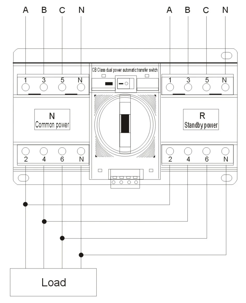
Normal, standby and load connections — select the image to enlarge.
Dimensions are identified by W, W1, L, L1 and H in each matching drawing. The dimensional and terminal configurations below are type-specific. Select the correct pole count and control version.
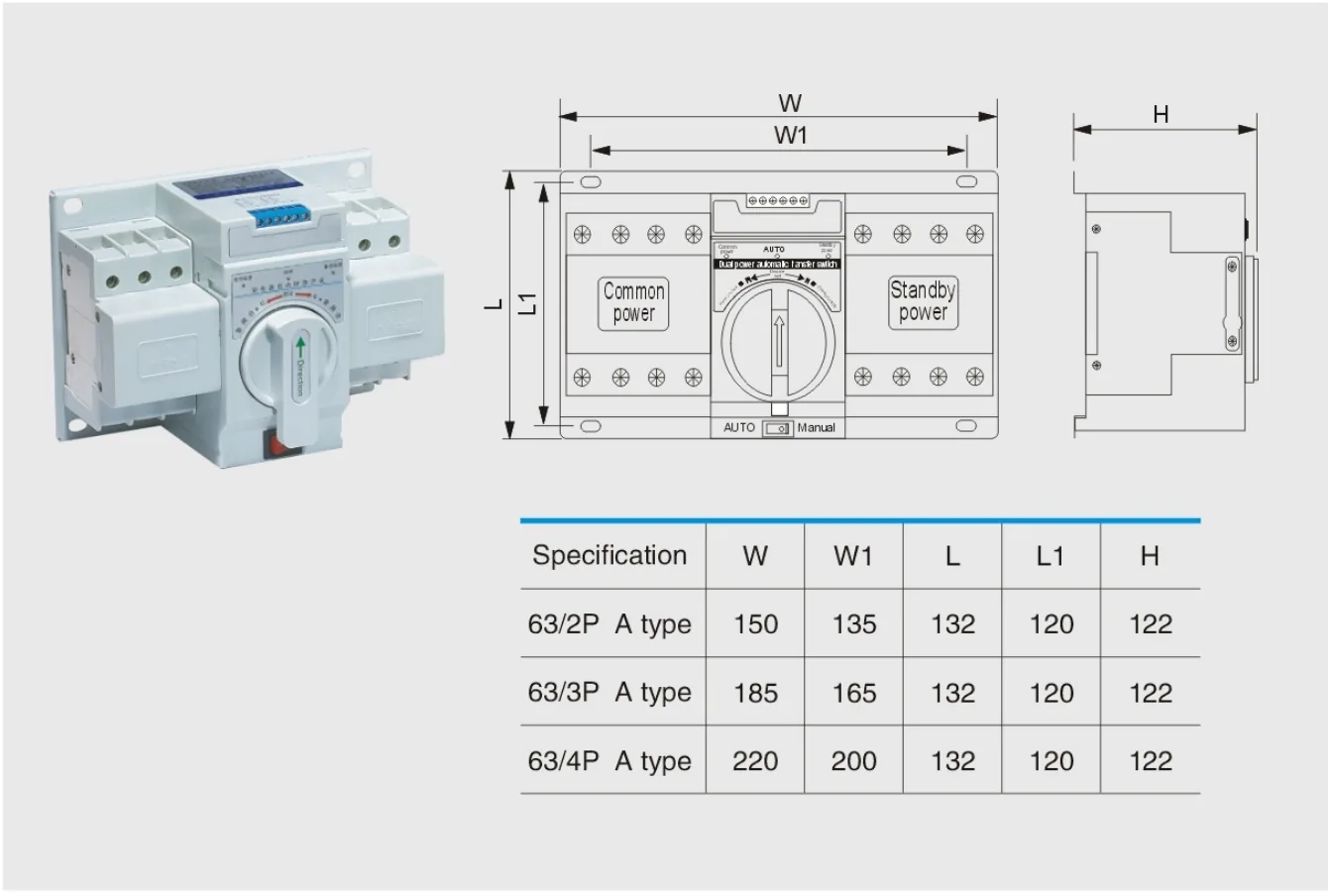
63-A overall and installation dimensions — select the image to enlarge.
| Pole configuration | Lettered dimensions |
|---|---|
| 2-pole | W = 150; W1 = 135; L = 132; L1 = 120; H = 122 |
| 3-pole | W = 185; W1 = 165; L = 132; L1 = 120; H = 122 |
| 4-pole | W = 220; W1 = 200; L = 132; L1 = 120; H = 122 |
The 63-A drawings show a basic indication version and a separate fire-control/generator version. Their terminal numbers have different functions; use the correct arrangement described below.
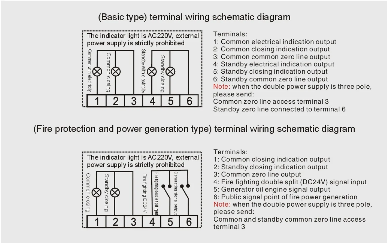
63-A terminal diagrams and connection notes — select the image to enlarge.
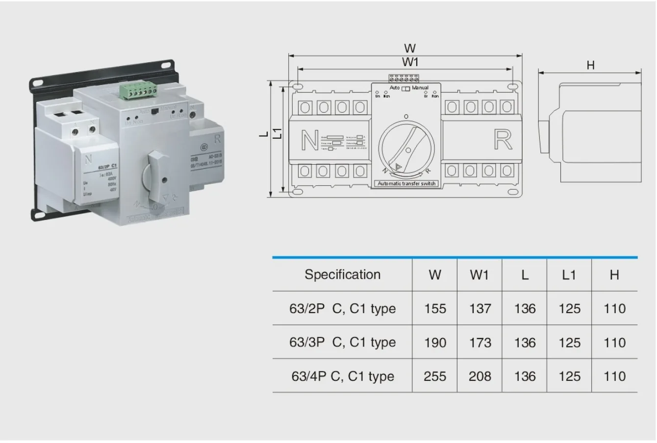
63-C / C1 overall and installation dimensions — select the image to enlarge.
| Pole configuration | Lettered dimensions |
|---|---|
| 2-pole | W = 155; W1 = 137; L = 136; L1 = 125; H = 110 |
| 3-pole | W = 190; W1 = 173; L = 136; L1 = 125; H = 110 |
| 4-pole | W = 255; W1 = 208; L = 136; L1 = 125; H = 110 |
The 63-C / C1 drawings show a basic indication version and a separate fire-control/generator version. Their terminal numbers have different functions; use the correct arrangement described below.
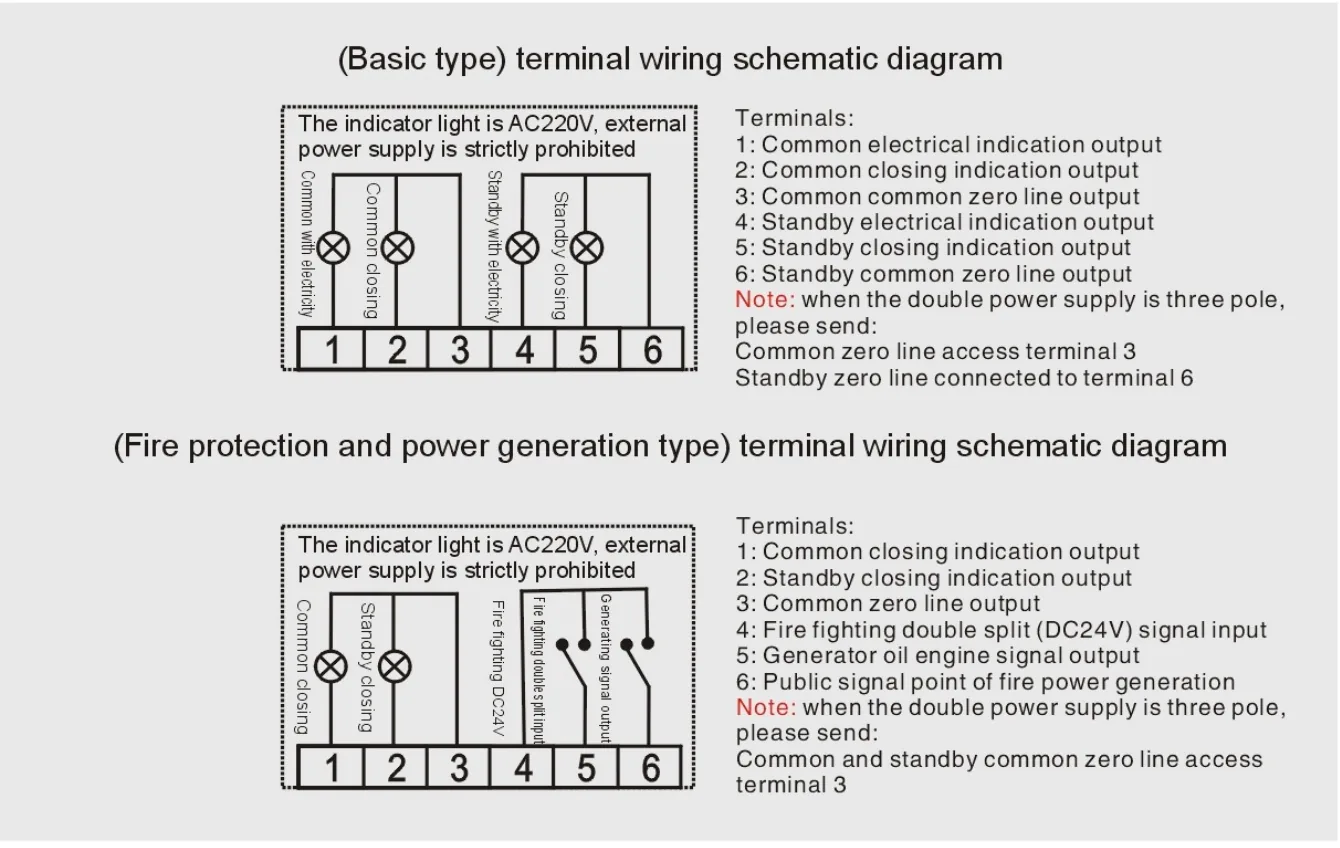
63-C / C1 terminal diagrams and connection notes — select the image to enlarge.
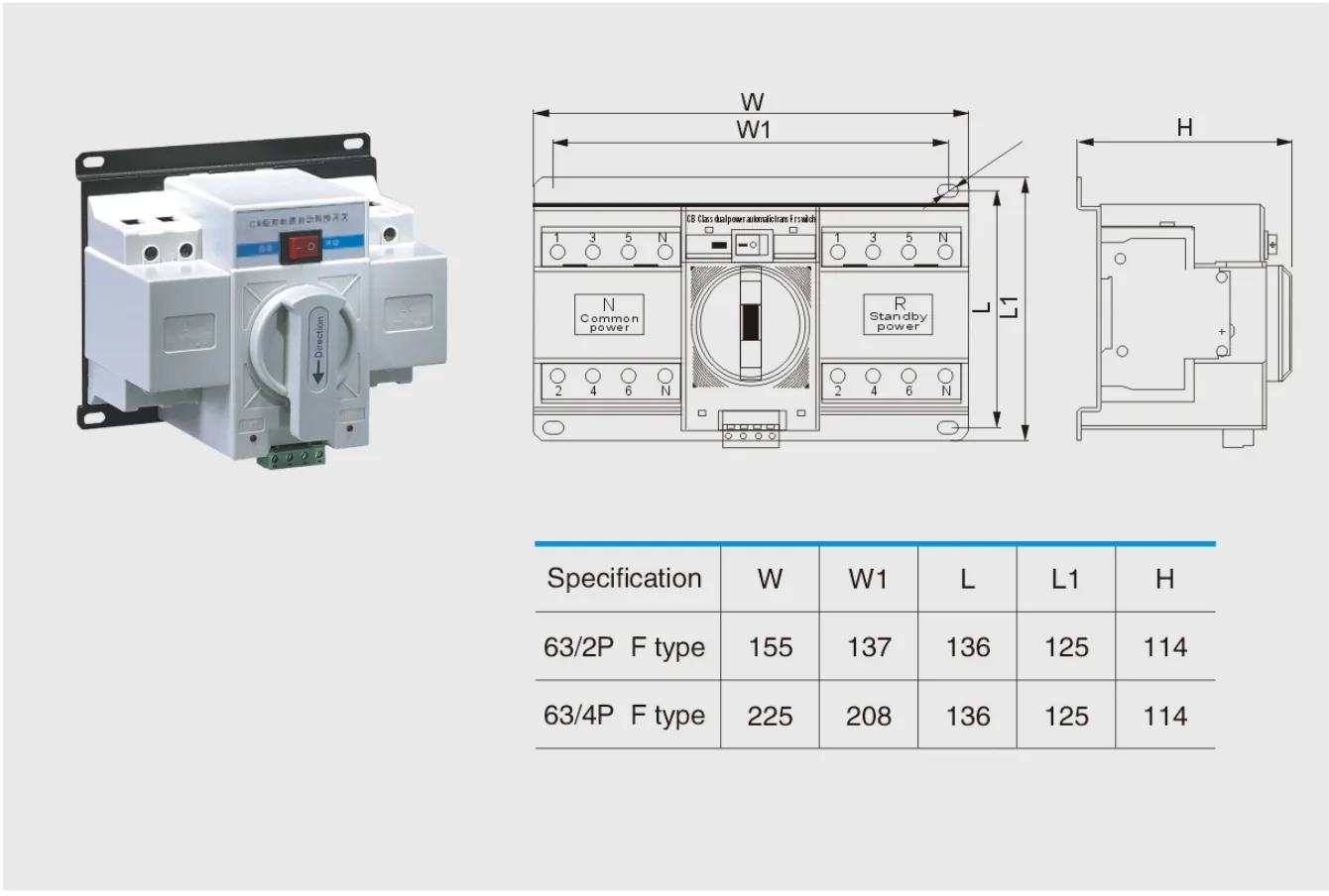
63-F overall and installation dimensions — select the image to enlarge.
| Pole configuration | Lettered dimensions |
|---|---|
| 2-pole | W = 155; W1 = 137; L = 136; L1 = 125; H = 114 |
| 4-pole | W = 225; W1 = 208; L = 136; L1 = 125; H = 114 |
The dimensional table lists 2-pole and 4-pole 63-F configurations. The general terminal version provides normal and standby closed indications. The intelligent terminal version also has a DC 24 V fire-control input.
The F-type indication drawings specify AC 230 V output. Terminals 2 and 4 are the neutral connections used for the indication circuits; do not connect neutral to a phase conductor.
| Terminal pair | Function |
|---|---|
| 1–2 | Normal closed-position indication; terminal 2 is neutral |
| 3–4 | Standby closed-position indication; terminal 4 is neutral |
| 5–6, intelligent version | DC 24 V fire-control input; polarity is shown in the matching diagram |
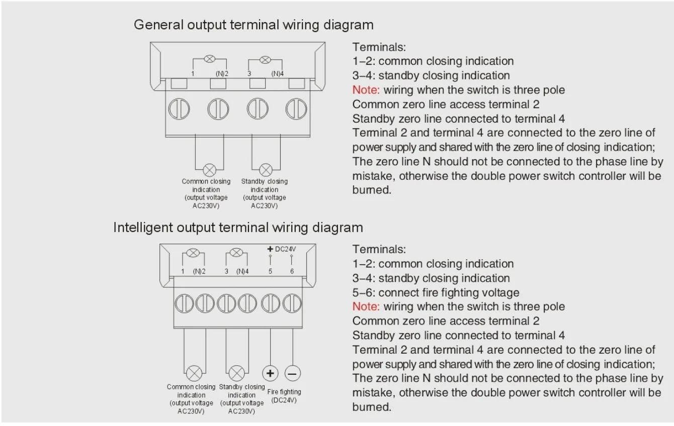
63-F terminal diagrams and connection notes — select the image to enlarge.
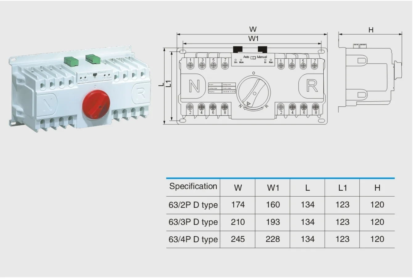
63-D overall and installation dimensions — select the image to enlarge.
| Pole configuration | Lettered dimensions |
|---|---|
| 2-pole | W = 174; W1 = 160; L = 134; L1 = 123; H = 120 |
| 3-pole | W = 210; W1 = 193; L = 134; L1 = 123; H = 120 |
| 4-pole | W = 245; W1 = 228; L = 134; L1 = 123; H = 120 |
The D-type terminal arrangement is distinct from the other types. Terminals 1, 2, 4 and 5 provide AC 220 V indication outputs; do not apply an external supply to these outputs.
| Terminal | Function |
|---|---|
| 1 | Normal closed-position indication |
| 2 | Normal supply-present indication |
| 3 | Normal indication neutral |
| 4 | Standby closed-position indication |
| 5 | Standby supply-present indication |
| 6 | Standby indication neutral |
| 7–8 | Optional DC 24 V fire-control input; confirm polarity on the supplied unit |
| 9–10 | Optional generator-start signal output |
For a 3-pole D-type unit, use terminal 3 for normal neutral and terminal 6 for standby neutral as shown. Confirm the fire-input polarity from the terminal markings and matching diagram supplied with the ordered D-type unit before wiring. Specify any non-standard fire-signal voltage when ordering.
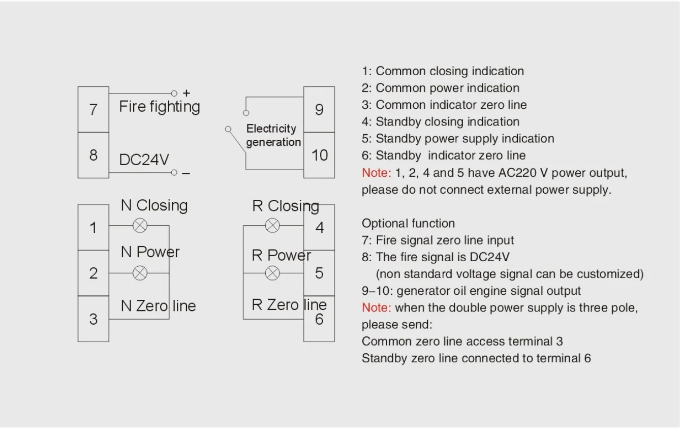
63-D terminal diagrams and connection notes — select the image to enlarge.
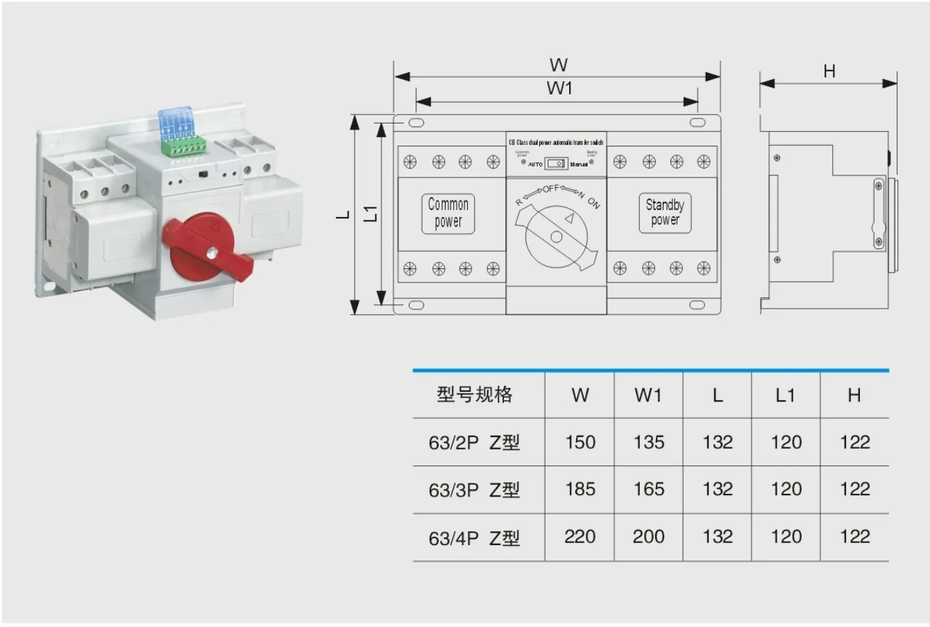
63-Z overall and installation dimensions — select the image to enlarge.
| Pole configuration | Lettered dimensions |
|---|---|
| 2-pole | W = 150; W1 = 135; L = 132; L1 = 120; H = 122 |
| 3-pole | W = 185; W1 = 165; L = 132; L1 = 120; H = 122 |
| 4-pole | W = 220; W1 = 200; L = 132; L1 = 120; H = 122 |
The 63-Z drawings show a basic indication version and a separate fire-control/generator version. Their terminal numbers have different functions; use the correct arrangement described below.
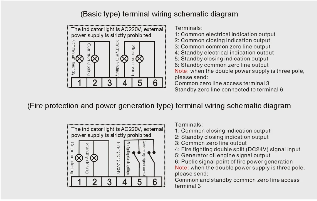
63-Z terminal diagrams and connection notes — select the image to enlarge.
Use the basic and fire-control/generator tables only with the corresponding A, C/C1 or Z diagram. Indication circuits are AC 220 V outputs; external power must not be connected to these outputs.
| Terminal | Function |
|---|---|
| 1 | Normal supply-present indication |
| 2 | Normal closed-position indication |
| 3 | Normal neutral connection |
| 4 | Standby supply-present indication |
| 5 | Standby closed-position indication |
| 6 | Standby neutral connection |
| Terminal | Function |
|---|---|
| 1 | Normal closed-position indication |
| 2 | Standby closed-position indication |
| 3 | Common neutral connection |
| 4 | DC 24 V fire-control double-OFF input |
| 5 | Generator-start signal output |
| 6 | Common fire-control and generator signal terminal |
For a 3-pole basic version, normal neutral connects to terminal 3 and standby neutral to terminal 6. For the illustrated 3-pole fire-control/generator version, the normal and standby neutral connections use the common terminal 3. The DC 24 V fire-control input and generator-signal terminals belong to that version only.
Please provide the following when requesting a quotation or placing an order:
Include the normal and standby supply details and any different normal/standby breaker-current requirements with the enquiry.
PC-class automatic transfer switch for mains/standby changeover. 3 or 4 poles, 20–3200 A series, with frame-specific ratings and wiring options.
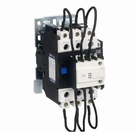
Inrush Current Protection: Integrated resistors/Reactors limit switching surges.
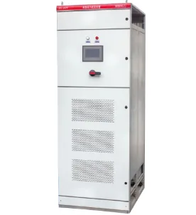
APF Active power filter device integrates one or multiple active power filter modules, a control unit, circuit breakers, contactors, a cooling system, and other core components into a standard industrial enclosure, forming a complete, plug-and-play harmonic mitigation solution.