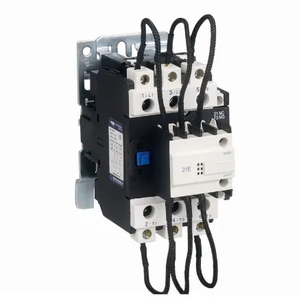
AC-6b Capacitor Duty Contactor
Inrush Current Protection: Integrated resistors/Reactors limit switching surges.
Vector VFD for three-phase AC asynchronous motors. SVC/V/F, PID, up to 16 speeds and RS485 Modbus-RTU. Select input supply and G/P duty.
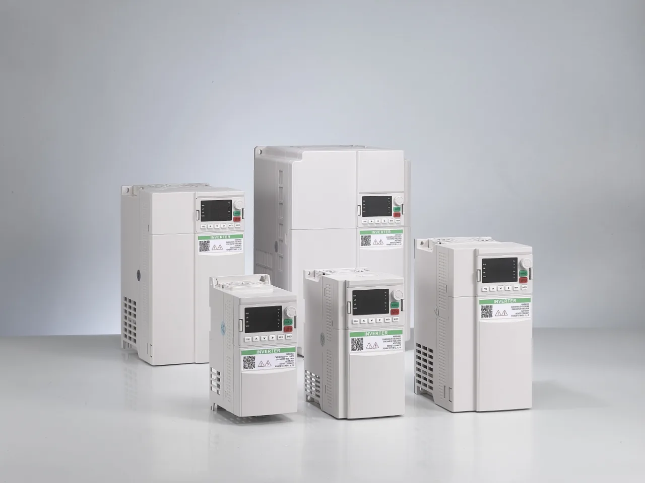
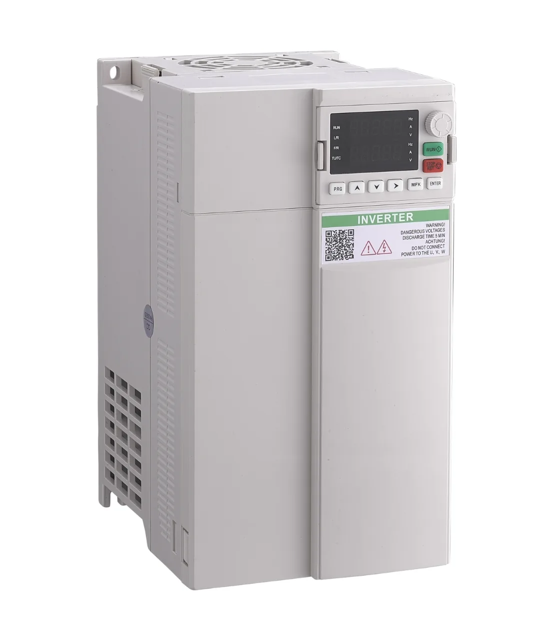
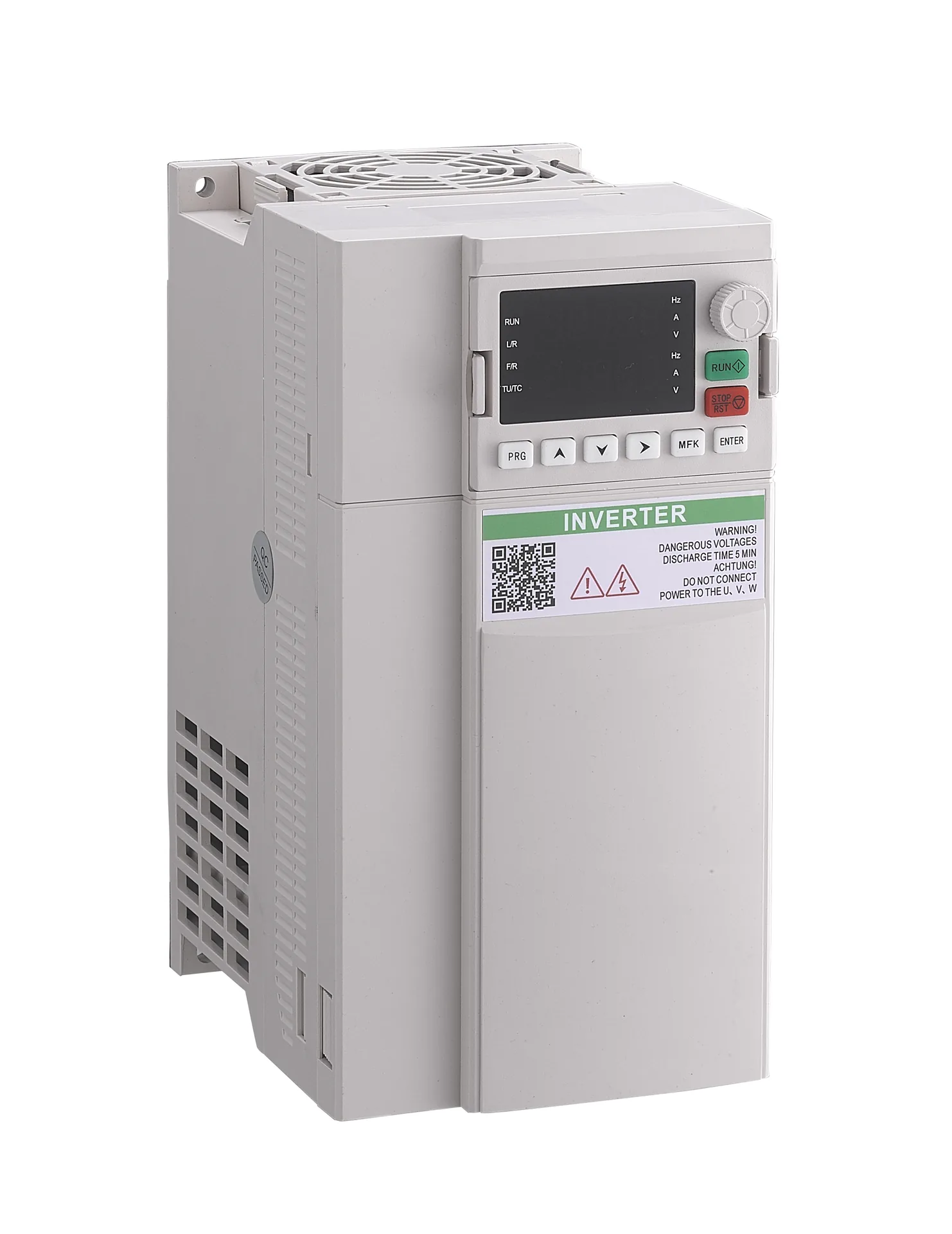
Model: High-performance Vector Frequency Converter
Vector VFD for three-phase AC asynchronous motors. SVC/V/F, PID, up to 16 speeds and RS485 Modbus-RTU. Select input supply and G/P duty.
| Input supply options | Single-phase 220 V or three-phase 380 V; select the required configuration |
|---|---|
| Motor type | Three-phase AC asynchronous motor |
| Control methods | Sensorless vector control (SVC); V/F control |
| Speed regulation range | 1:100 (SVC); 1:50 (V/F) |
| Process / multi-speed control | Built-in PID; up to 16 speeds via simple PLC or control terminals |
| Communication | RS485 / Modbus-RTU |
| G-duty overload | 150% rated output current for 60 s; constant-torque duty |
| P-duty overload | 120% rated output current for 60 s; variable-torque duty |
| Run command sources | Operation panel, control terminals or serial communication |
| I/O overview | 5 DI, 2 AI, 2 open-collector outputs, 2 AO and 2 relay outputs; high-speed functions share channels |
A vector variable frequency drive for speed control of three-phase AC asynchronous motors, with built-in PID, multi-speed operation and RS485 Modbus-RTU communication.
Select the input supply and drive current to match your motor and load. G duty is intended for constant-torque applications; P duty is intended for variable-torque applications. Each duty has its own overload rating.
Control Functions
| Function | Specification |
|---|---|
| Motor control | Sensorless vector control (SVC) and V/F control |
| Speed regulation range | 1:100 (SVC); 1:50 (V/F) |
| SVC speed stability | ±0.5% |
| G-duty overload | 150% rated output current for 60 s; constant-torque loads |
| P-duty overload | 120% rated output current for 60 s; variable-torque loads |
| Carrier frequency | 0.5–16 kHz |
| Torque boost | Automatic torque boost; manual setting 0.1–30.0% |
| V/F characteristics | Linear, multi-point and square curves |
| Acceleration / deceleration | Linear or S-curve; four time sets; 0.0–6500.0 s |
| DC braking | Starting frequency: 0.00 Hz to the configured maximum; time: 0.0–36.0 s; current setting: 0.0–100.0% |
| Jog operation | 0.00–50.00 Hz; acceleration / deceleration: 0.0–6500.0 s |
| Process control | Built-in PID for closed-loop process control |
| Multi-speed operation | Up to 16 speeds via the simple PLC function or control terminals |
| Timing control | 0.0–6500.0 min |
| Run command methods | Operator panel, control terminals or serial communication |
| Frequency setting | Digital setting, analog voltage, analog current, pulse or serial communication, according to configuration |
| Voltage regulation | Automatic voltage regulation (AVR) |
| Current and torque management | Overvoltage / overcurrent stall control, fast current limiting and torque limiting |
| Display | Two groups of operating data can be monitored simultaneously |
Protection functions include input / output phase loss, overcurrent, overvoltage, undervoltage, overheating and output short-circuit protection.
Match both motor power and rated current when selecting a drive. Choose the required input supply and duty rating for the application.
Single-Phase 220 V Input
| Power (kW) | Input (A) | Output (A) |
|---|---|---|
| 0.75 | 8.2 | 4.5 |
| 1.5 | 14 | 7 |
| 2.2 | 23 | 9.6 |
Three-Phase 380 V Input — G Duty
| Power (kW) | Input (A) | Output (A) |
|---|---|---|
| 0.75 | 2.4 | 2.1 |
| 1.5 | 4.6 | 3.8 |
| 2.2 | 5.8 | 5.1 |
| 4 | 10.0 | 9.0 |
| 5.5 | 15.0 | 13.0 |
| 7.5 | 20.0 | 17.0 |
| 11 | 26.0 | 25.0 |
| 15 | 35.0 | 32.0 |
| 22 | 46.5 | 45.0 |
| 30 | 62.0 | 60.0 |
| 37 | 76.0 | 75.0 |
| 45 | 92.0 | 91.0 |
| 55 | 113 | 110 |
| 75 | 157 | 150 |
P-duty electrical ratings are specified separately for the selected configuration. Single-phase 220 V describes the input supply; the drive is intended for a three-phase AC asynchronous motor.
Control Interfaces
| Interface | Specification |
|---|---|
| Digital inputs | 5 programmable inputs |
| High-speed input | Up to 50 kHz; shared with the fifth digital input |
| Analog inputs | 2 inputs; specify the required voltage or current signals when selecting the configuration |
| Analog outputs | 2 outputs; 0–10 V, 0–20 mA or 4–20 mA output modes, according to configuration |
| Open-collector outputs | 2 outputs; one can operate as a high-speed pulse output up to 100 kHz |
| Relay outputs | 2 |
| Communication | RS485 / Modbus-RTU |
| Auxiliary 10 V supply | Maximum output current: 10 mA |
| Auxiliary 24 V supply | Maximum output current: 150 mA |
| External operator panel | External keypad connection for operation and parameter access |
High-speed functions share the designated input or output channel. Include your PLC signal types, communication requirements and required I/O assignments with your enquiry.
Environment and Derating
| Condition | Requirement |
|---|---|
| Installation location | Indoor, well ventilated; protect from direct sunlight, dust, corrosive or flammable gases, oil mist, steam, dripping water and salt |
| Ambient temperature | −10 to +40 °C without temperature derating |
| Temperature derating | Above 40 °C: reduce the rating by 1.5% per 1 °C increase; maximum 50 °C |
| Relative humidity | Below 95% RH, non-condensing |
| Altitude | Up to 1,000 m without altitude derating |
| Altitude derating | Above 1,000 m: reduce the rating by 1% per additional 100 m, up to 3,000 m. Contact us for higher-altitude applications |
| Vibration | Less than 5.9 m/s² (0.6 g) |
| Storage temperature | −20 to +60 °C |
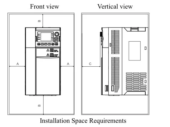
Space around a single drive
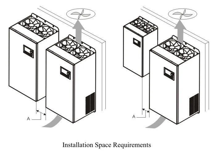
Side-by-side installation and cooling airflow
Heat deflection for stacked drives
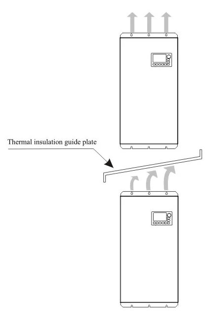
Required clearances, overall dimensions and mounting-hole positions depend on the selected frame. Request the dimensional and mounting drawing before finalising the cabinet layout.
Power Terminal Functions
| Terminal | Connection |
|---|---|
| R / S / T | Input power for the three-phase 380 V configuration |
| L / N | Input power for the single-phase 220 V configuration |
| U / V / W | Output to the three-phase AC asynchronous motor |
| PE | Protective earth connection |
The input arrangement depends on the selected drive configuration. Use the wiring drawing supplied for the selected unit. Installation and wiring must be carried out by qualified electrical personnel. Disconnect power, observe the discharge time on the product label and connect protective earth before work. Never connect the supply to U / V / W.
The braking-unit arrangement depends on the drive configuration. An external braking resistor is selected separately; configurations without a built-in braking unit also require an external braking unit when resistor braking is needed.
For rapid or frequent stopping, provide the motor and load information, required stopping time and braking cycle so the resistor and braking-unit requirements can be selected.
The LED operator panel displays running status, frequency, electrical values, parameter codes and fault information. Two groups of operating data can be displayed simultaneously.
LED operator panel
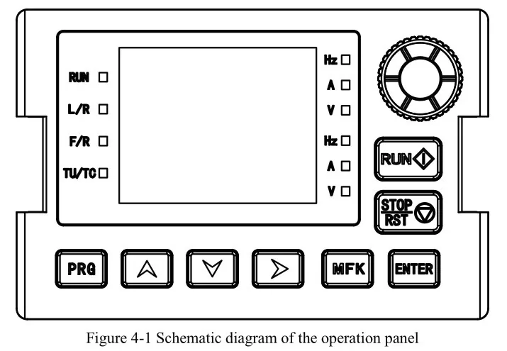
Panel Keys
| Key | Function |
|---|---|
| PRG | Open or close the primary parameter menu |
| ENTER | Enter a menu level and confirm a parameter value |
| ▲ | Increase a value or function code |
| ▼ | Decrease a value or function code |
| ▶ | Cycle displayed parameters or select the digit being edited |
| RUN | Start the drive in keypad-control mode |
| STOP / RST | Stop operation or reset a fault |
| MFK | Multifunction key; assignment is set with H7-01 |
Status Indicators
| Indicator | Meaning |
|---|---|
| RUN | Off: stopped. On: running |
| LOCAL / REMOTE | Off: panel control. Steady: terminal control. Flashing: communication control |
| Forward / reverse | Illuminated direction indicator: reverse operation |
| Tuning / torque / fault | Steady: torque-control mode. Slow flashing: tuning. Rapid flashing: fault |
Display Units
| Indicator | Displayed quantity |
|---|---|
| Hz | Frequency |
| A | Current |
| V | Voltage |
| Hz + A | Speed |
| A + V | Percentage |
The upper display cycles through operating values with the shift key. The lower display is configured using H7-17 and H7-18, with monitoring values in the U0 group.
Parameter access uses three levels: function group, function code and setting value. Use PRG to access the menu, the arrow keys to select or adjust a value and ENTER to confirm.
Contact us for the applicable English user manual, wiring drawing, dimensional drawing and configuration details. For drive selection, provide the motor nameplate, supply voltage and phases, load type, speed range, control signals, braking needs and installation conditions.
How do I choose the drive rating?
Use the motor nameplate power and current, input supply and load duty. Include acceleration, stopping and temperature / altitude conditions when selecting the configuration.
Can a single-phase supply drive a single-phase motor?
The single-phase 220 V option refers to the input supply. This drive is intended for three-phase AC asynchronous motors; match the motor and output configuration when selecting.
Can the drive connect to a PLC?
RS485 Modbus-RTU and digital, analog and relay I/O support control-system integration. Specify the signal types and communication requirements for your application.
Are braking components included?
The braking arrangement depends on the selected configuration. Specify the load, stopping time and braking frequency so the required components can be selected.
What should I send with a quotation request?
Send the motor nameplate, available supply, application, control and braking requirements, installation conditions, quantity and destination country.
Inrush Current Protection: Integrated resistors/Reactors limit switching surges.
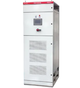
APF Active power filter device integrates one or multiple active power filter modules, a control unit, circuit breakers, contactors, a cooling system, and other core components into a standard industrial enclosure, forming a complete, plug-and-play harmonic mitigation solution.
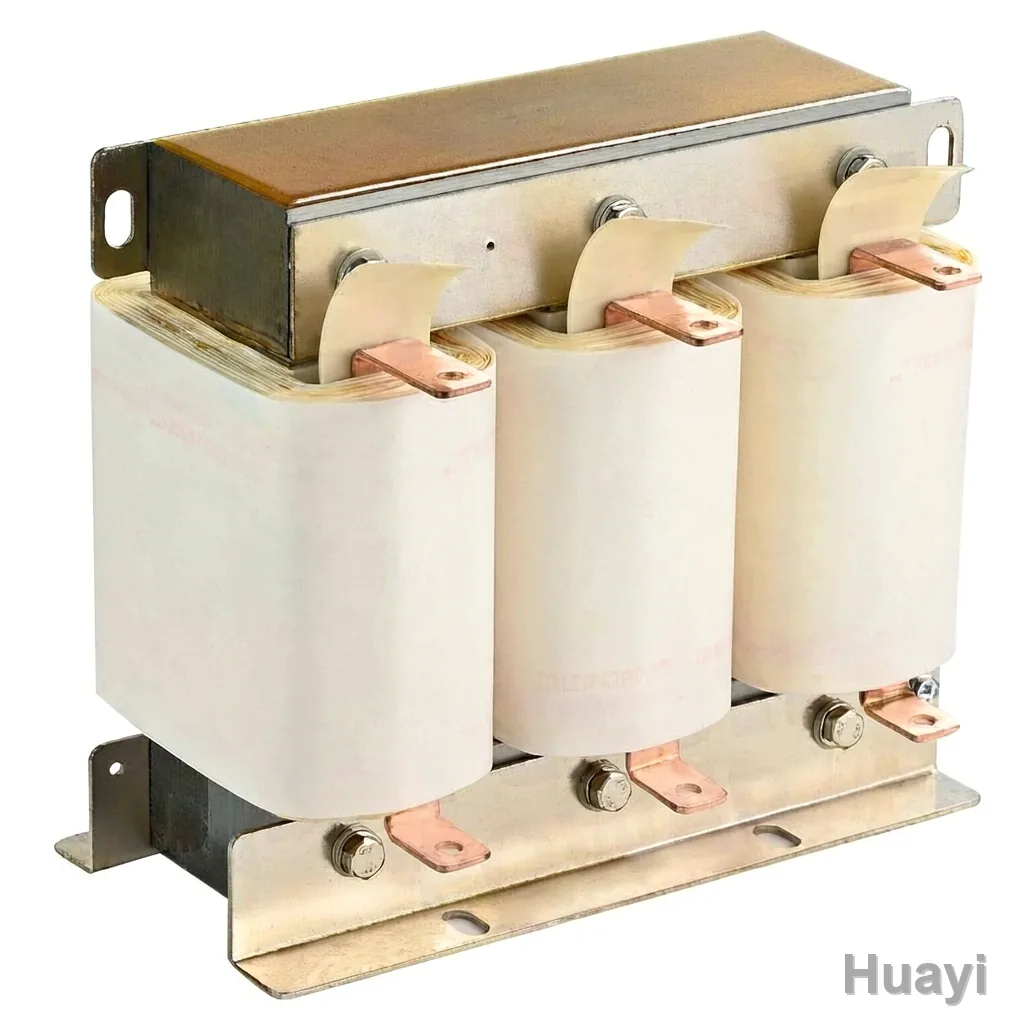
our Detuned Harmonic Filter Reactors are built using premium, low-loss silicon steel cores, high-grade winding insulation, and precision engineering techniques.